QuaSH
In which we revisit a 5 year old PIC project and develop it to be far more interesting than we had ever imagined.
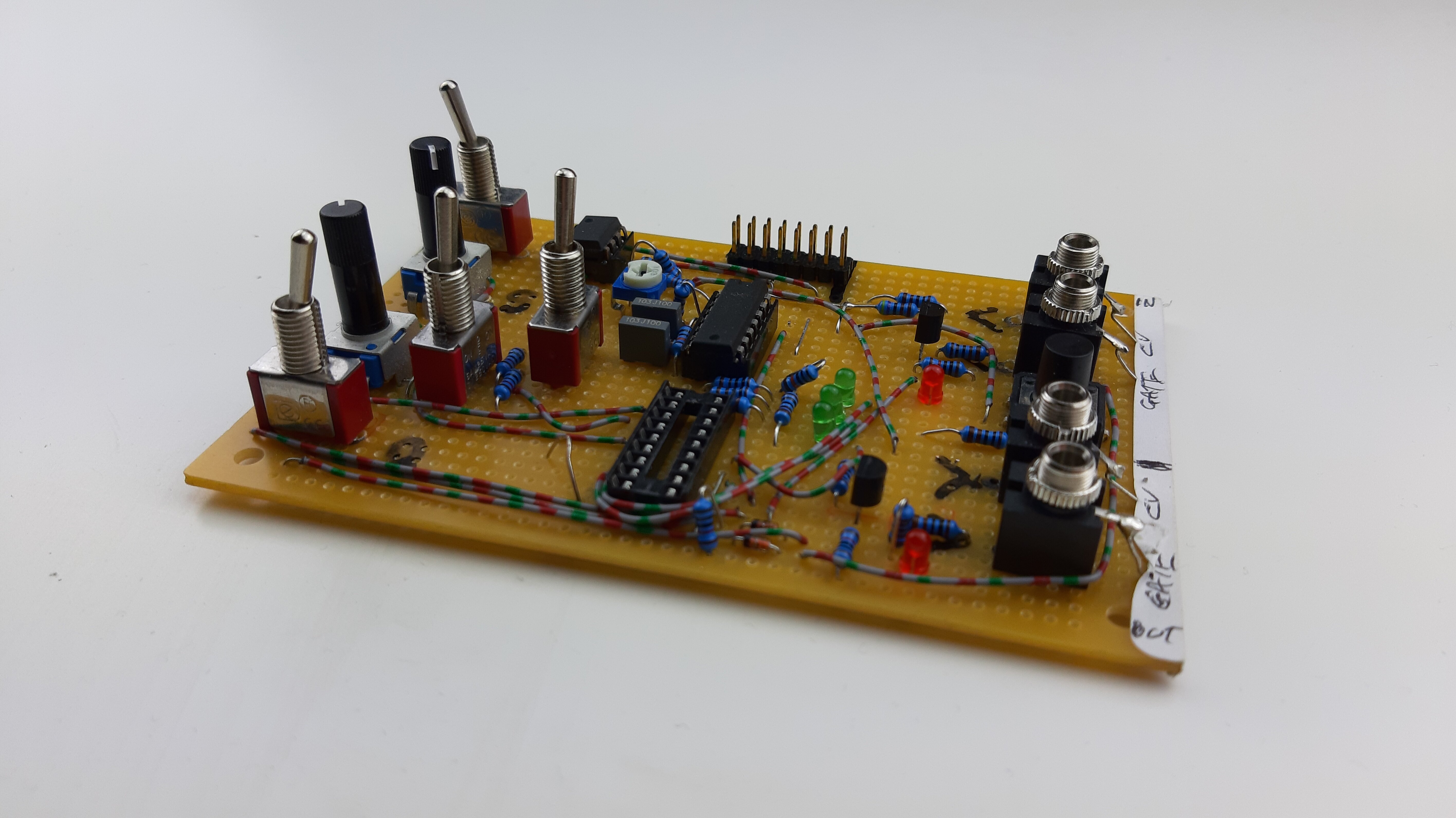
Back in 2013/4, whilst developing the Bartos Flur for my A-Level Electronics Project, I developed a very simple PIC program that worked as a chromatic quantiser. We nicknamed it ‘QuaSH’, though we didn’t actually have a use for it. Whilst developing Little Melody, we had need of a quantiser again, and so I reviewed and reused my old code. One thing lead to another, and we decided to expand Little Melody’s quantiser into it’s own full module, too.
QuaSH grew out of two things: A throwaway idea we made for Bartos Flur purely to meet my academic requirements, and a feature we were developing for Little Melody.
From Little Melody to QuaSH
To make Little Melody simpler to use, we realised that we needed a quantiser. I looked back to my old code from 2014, and whilst I liked the implementation concept, I decided to rewrite the code as the actual implementation was flawed.
The quantiser that I had designed is fairly novel in it’s technical implementation. To be able to output a 5 octave range, you need to be able to output 61 distinct values at specific levels. Unfortunately, when you’re working with very low bit numbers (like may be found on a cheap PWM unit or DAC unit), this means that you’d have error where the outputted value doesn’t correctly line up with the required value, meaning the note feels out of tune.
To illustrate the problem, imagine we were using a 6-bit DAC. Let’s cherry pick the example of the 50th value in our range - the D from the fifth octave - which requires us to output 4.166 volts. The closest that a 6 bit DAC can output would be either 4.206 volts, or 4.126 volts. Both possible values are 0.040 volts incorrect. The difference between two distinct notes is just 0.081 volts, so both possible values are roughly ~50% wrong.
Having a higher precision DAC can mitigate the issue, but this is often expensive. Martin Doudoroff measures this problem in various modules with his ‘nominal accuracy’ field in this comparison table. It’s an important issue!
My implementation attempts to sidestep the DAC precision issue by outputting in the lower 61 values of the 64 value range. (ie representing a value that “should be” 5 volts as 4.84 volts) and then using amplifiers with a tiny gain to ‘correct’ the value to the correct range. By doing this, the DAC doesn’t ever have to try to output ‘in between values’ - it’s always outputting an exact, correct value. Our method has the downside that it uses additional hardware and that the amplifier needs to be trimmed to the correct gain, but it’s a solution that I liked and I decided to stick with it.
Once we had the quantiser built for Little Melody, we threw around the idea of using that chromatic quantisation functionality as it’s own standalone module. I realised that we had a spare input pin on the Little Melody PIC that we weren’t planning on using, and had the idea that we could use it to change what the function of the inputs and outputs of the PIC do. The pin would be used to determine which program the PIC should execute.
A quantiser doesn’t need any of the Little Melody specific features like division selections or modes, it needs scale and chord selections. It has totally different input and output requirements. Essentially, the idea would be: Plug the chip into the Little Melody hardware and it runs the same code as always, but if you plug it into QuaSH hardware, it runs completely different code to function as a quantiser. We could have achieved the same thing with two completely different programs on two different chips, but the advantage of this is that we only need to stock one PIC part, meaning the project is less of a risk/investment for Frequency Central.
Coding Issues
Development of QuaSH turned out to be pretty tricky because of our ‘two programs on one chip’ concept. I found that changing a section of code to implement a feature for QuaSH sometimes broke Little Melody in some way. I had to test both modules every time I made a change to either, which was slow and cumbersome.
In hindsight, I went about implementing this ‘two programs on one chip’ idea the wrong way. It would have been better to keep the code for QuaSH and Little Melody completely separate. The two programs should never execute the same piece of code if it’s possible to avoid it. Unfortunately, due to the way the ideas evolved, that wasn’t what I did in practice. Originally, the QuaSH quantiser was only subtly different from the Little Melody quantiser and it made sense to reuse the code. As our requirements developed, the two programs became radically different. I ended up having little snippets of code everywhere saying “If Little Melody Do X, If QuaSH do Y”. It became a mess and I wish I had done things differently.
There were times when the ‘two programs on one chip’ concept didn’t look like it could even be used. At one point I had issues with the PIC turning on and running the code for the wrong module, which was very frustrating to solve and filled me with feelings of dread. I tried various methods to correct course if the PIC accidentally became the wrong module, but in the end the simplest and most reliable solution seemed to be “wait a few seconds before deciding which module to be”.
As both programs grew, I eventually reached the point where the total length of the code surpassed 2048 instructions. This meant that my code crossed a page boundary and due to a limitation in the PIC hardware, the program counter can’t uniquely identify each instruction any more. Attempts to access the program instruction at location 2049 will give you instruction 1, 2050 gives you 2, etc. You have to take special measures to keep the program working correctly.
It was my first time encountering this issue, and I didn’t notice the warning in my console (“Message[306] : Crossing page boundary – ensure page bits are set.”). The console goes by so fast, and is packed with messages about things I have already addressed. I often don’t pay too much attention to it. As a result, I was completely perplexed as to why my code wasn’t working. Making changes to try to fix a broken feature caused another to break seemingly at random - my changes were pushing more and more code into the ‘inaccessible zone’ that the program counter couldn’t reach. Once I figured out what was going on, it was easy to fix the problem. I moved a big chunk of code to the second code page and added pagesel commands before the goto instructions that took me there.
QuaSH features
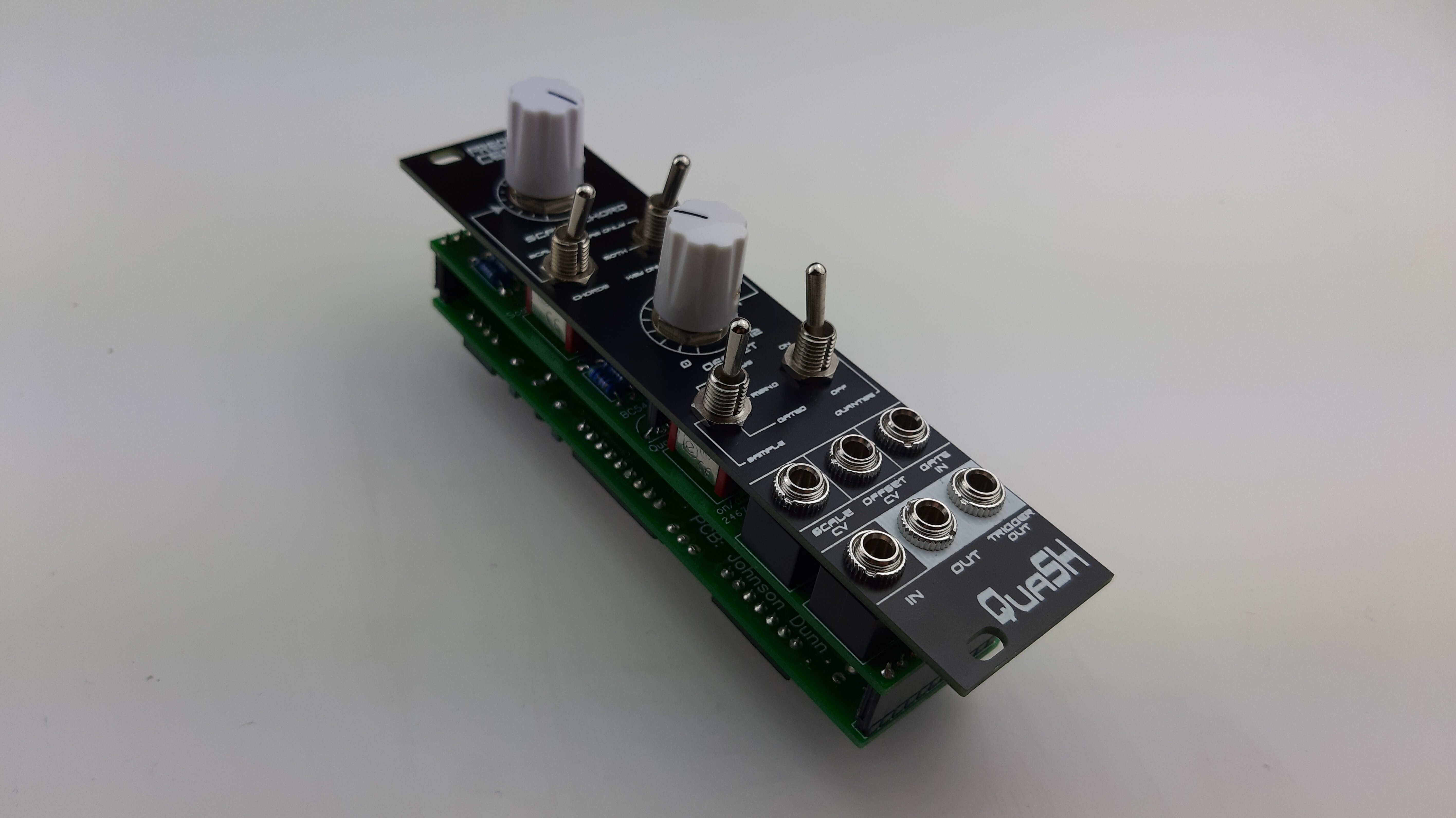
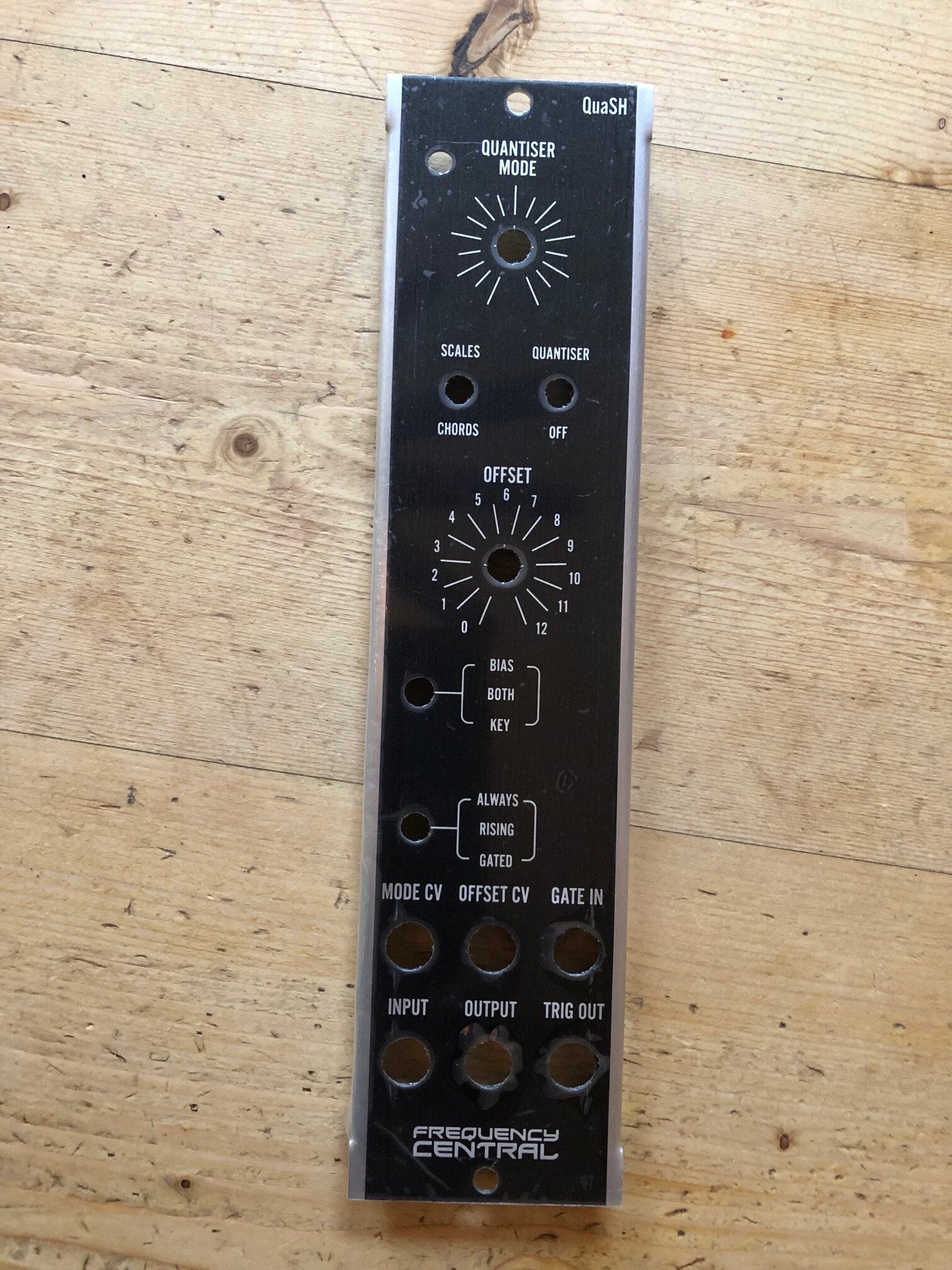
QuaSH ended up with quite a respectable feature set, in my opinion. It quantises to one of 16 scales or 8 chords and can output across 5 octave. You can use the offset input to change the pattern subtly, either by adding voltage as a bias, or by using it to set the key of the scales and chords - or both! Sampling only happens when you want it to, as we included a gate input and a switch to select between sampling always, only when the gate is high, or only on the rising edge.
A feature we added very close to the end of development was the ability to turn the quantiser off and just use the module as a ‘pure’ sample and hold. When in ‘sample on rising edge’ mode, it acts like a classic sample and hold, whilst when it’s in ‘sample whilst gate high’ mode it acts a bit like a ‘mute’. When in ‘always sample’ mode, the module is essentially bypassed. The feature is a bit lo-fi as our output from the PIC isn’t a great resolution, but it’s an option for people to make use of.
Conclusion
QuaSH ended up being a really fun module. It’s one of the first Eurorack modules that I’ve had fun playing with on my own. It’s so simple to create something that sounds good - it doesn’t require musical knowledge or intuition at all. It’s innately musical because it quantises to known scales and chords, so even a non-musician like myself can use it to create something that sounds good. When I use it, it reminds me of Portal 2’s Robot Waiting Room, and it brings me a lot of joy to understand how I could make music like that.
A demo of using QuaSH with a simple triangle LFO is below:
Another project all finished up! 🎛
— Jet Holt (@JetroidMakes) October 16, 2019
Quantised Sample & Hold circuit, using a PIC16F88 programmed in Assembly. 👨💻
Converts continuous signals into scales and chords. 🎧 pic.twitter.com/p2P2xqhTcr
At the time this article was written, QuaSH already has a Eurorack prototype, and plans for a MU module are on the way too. Watch this space for more development, and information when we release it.
P.S. I'm late to the party, but I recently got a twitter account that you can follow here.


