Seismograf
How I developed Seismograf, a drum sound module.
When revamping the waveforms on the Chronograf, one of the sound functions we created was an exponentially damped sine wave. I looked up the Roland TR808 Bass Drum waveform and tried to mimic it using mathematical formulas as best I could. The result was incredibly promising, and has a pleasing thud, just like a Bass Drum. I auditioned out various different versions of the damped sine wave in the space of Chronograf’s other waveforms, and essentially created a drum module with very similar sounds.
Polygraf, our grid editor module, was designed to tell other modules when to trigger. In particular, we envisioned it being used to trigger drum modules. The Chronograf-based drum sounds and the concept of Polygraf came together, and it suddenly made sense to develop the drum sounds chip further and make a dedicated drum module.
Damped Sines
We had the idea of taking the Chronograf waveform playback code, stripping out all of the Chronograf-specific functionality (clock outputs, modes, etc), and seeing what a module would sound like with different versions of exponentially damped sine waves. The formula I had created for the Chronograf allowed me to vary the number of peaks present in the waveform. The version in Chronograf had 38 peaks, and I fitted this new chip with damped sine waves with 6, 14, 22, 30, 38, 46, 54, and 62 peaks. Because it was essentially just a rework of the Chronograf, I continued to use the Chronograf perf board prototype.
This experiment, dubbed the ‘DampedSineGraf’, sounded okay. It was interesting… but that’s all it was. We couldn’t really make a module out of it, and many of the sounds felt quite weak. We wanted to give Frequency Central’s customers something better.
Modern Hardware
Whilst developing the Chronograf, we had ordered some PIC16F1764 chips (We had thought that perhaps the cause of our bad sound quality might be due to output rate, or due to PWM filtering problems - the 16F1764 could output 4 times as fast, had a DAC that we could use instead of PWM, and had the same pinout as the PIC16F684 we were already using). The 16F1764 is a much newer chip whilst the 16F684 is more than a decade old; there’s no real good reason to use the 16F684 anymore. We used it for Chronograf because we had some, and because we began developing it before these newer chips we released.
The 16F1764 had twice as much memory as the 16F684 that we had used for the Damped Sine experiment, so in theory could hold twice as many sounds, or have sounds with twice as many steps. The 16F1764 also had a Flash Program Memory Control module, which means that you can access all 14 bits stored in an instruction word; this is a big deal, as it allows me to use the memory in the chip much more efficiently.
Previously I had to use hundreds of instructions in a row (eg retlw .255), and you would jump to a specific index of those instructions, and it would return with the value specified by the instruction. This meant that the 14 bit word was used to provide an 8-bit value, the remaining 6 bits were used to identify that it was a retlw instruction. Being able to use program memory control meant that I essentially had an additional 75% extra storage for every word I dedicated to storing data in.
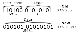 Image example of storing numbers using the old and new methods
A side effect of this was that it meant I could use 10-bit resolution (the limit of my analogue peripherals) for my output, which effectively quadruples the number of positions the sound can be in, improving quality.
Better Sounds
Feeding this more advanced chip with Damped Sine waves wasn’t going to make it that much more exciting. I decided to look up what the DR55 waveforms looked like. The DR55 was an early drum machine and my dad owns a one - he had shown it to me whilst I originally developed the Polygraf a few years back. It’s got both the read-write pattern functionality of Polygraf, and a set of Bass Drum, Snare Drum, RimShot, and HiHat sounds, all in one small device. I hoped that by looking at it’s waveforms, I could try to figure out a way to emulate them in my spreadsheets with formulae.
I downloaded samples in WAV format, then used a simple Python script I found from StackOverflow to view them.
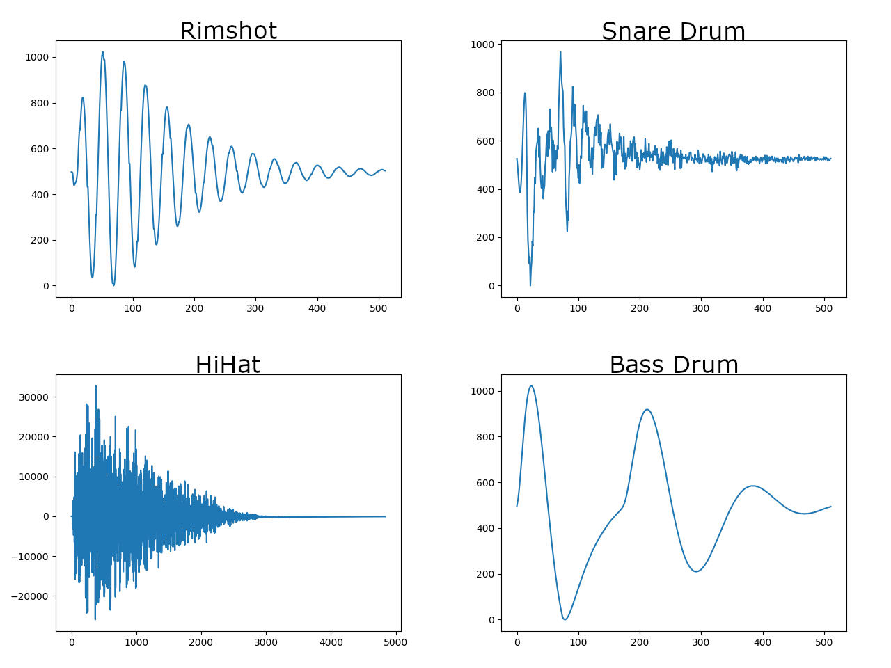 Waveforms sampled from the DR55
I’d never really looked at sound waveforms before, so it was very interesting to see these. The Bass Drum and RimShot were familiar, but the HiHat and Snare sounds were pretty wild, like nothing I knew how to realistically emulate using formula (Obviously Fourier proved that you can recreate any sound by mixing the correct sine waves together, but I wouldn’t know where to start with that.)
WAV manipulation
I decided to write a script that can convert a WAV file into a set of data that the PIC can recognise. If I created my script to be flexible on the number of resolution (amplitude) bits, and the number of steps (samples per sound), then I could experiment with different qualities of sound and it may have uses outside of just this one project. The python wave library was really helpful here.
A problem I had to solve here was I suspected a lot of WAV files would have short clips of silence before and after the actual sample. I was able to solve this by tracking forwards and backwards, calculating a moving average as I go, and detecting when the value first changed significantly from the average (I consider a 1% change significant).
At this point, I (hopefully) have isolated the actual sound portion of the waveform. However, it’s almost certain that the number of samples I have remaining is different from the number of samples I can store. We can calculate a ratio that represents how many we can store to how many are remaining, and then use that to know how many samples to skip between each sample we keep (or how many samples to repeat if we have more space than the WAV has samples).
My algorithm here is really simple, but it works quite well, and a variety of samples were able to be reproduced accurately. Other samples, particularly those with high frequency components, just sounded like noise. I found that it almost became a game of “luck” about whether we could adequately reproduce a sample or not.
I tried to ‘audition’ sounds, to see how good or bad they sounded. I wasn’t the best judge at this, so I deferred to my father’s musical ear. Some sounds that I thought sounded terrible he loved, which I found quite peculiar. In particular, I felt that the frequency range went waaaay too low, to the point that it was garbled and you started hearing this high frequency noise, but he thought it was good like that. What?!
Storage Plans
On the 16F1764, I had 4096 14-bit words to use. Some of these I necessarily had to give to the actual program, but I wanted to dedicate most of it to data.
I definitely wanted eight sounds - eight is a nice number in PIC terms as it is a multiple of two. I also kind of wanted 512-step sounds. Now, looking at 4096/512, you see it exactly divides into 8. This means that if I evenly distribute my words across samples, I will surely run out of space for my program, which needs it’s own 256 word lookup table for rate control (for the in-built timer), let alone the code to make everything work. Bummer.
However, that is ignoring the fact that we’re only using 10-bit samples and our words can store 14-bit data! If we play it smart, we can store extra sample data across the upper 4 bits that we aren’t using. In this way, we get an extra ‘compressed’ sound for every 2.5 ‘normal’ sounds.
If we have six ‘normal’ sounds, we can have two ‘compressed’ sounds in the upper four bits. This leaves us able to have a full 1k words for our program, which is really nice and plentiful. The only caveat is that reading the compressed sounds will be slightly slower as you have to essentially ‘read’ 3 samples and then recombine them using bitmasking and bitshifting to get the correct value.
I’ve tried to visualise how I stored the memory on the 16F1764, below.
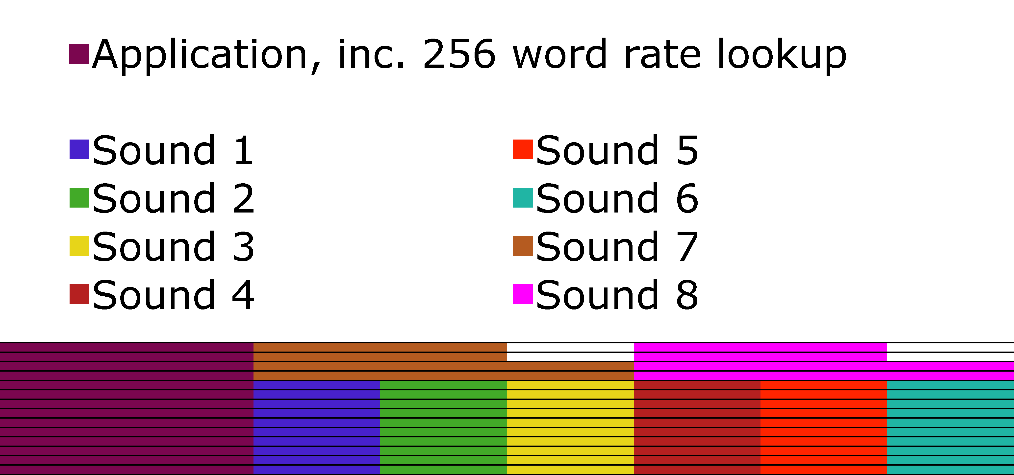 Shaded regions represent program memory. Rows represent bits. Blocks are 512 words wide.
Now, obviously this complicates matters. Before I could just convert my wave file into a set of data and paste things in, but now I need to recombine them. I wrote a quick python script that recombines these nicely, meaning I just have to list the filenames of the WAV eight files I want to use, and it spits out the correct data to paste into my application.
Distortion and Bitcrush
Just being able to play back sounds is great, but it’s quite a limited feature set.
It’d be really nice if we could add some distortion (ie variable gain, with clipping) or bitcrush (ie reducing our sample quality from 10 bit down to 8-2 bits).
Bitcrush was really obvious how to implement as it’s just a matter of bitmasking away the data we don’t want.
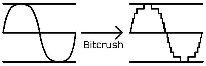 Graphical representation of Bitcrush.
Distortion is trickier; I couldn’t think of a cheap way to do gain without using some kind of floating point multiplication. I mulled it over for a few days, and the solution came to me in the shower (isn’t that so often the case?). If we divide through to get a 1/32th (for example) of the amplitude, then we can add that value back to the original to have a 1.03x gain. Add it again, and we have a 1.06x gain. If ever we overflow (ie reach a value higher than the maximum value we can represent), then we want to clip, so we just return the maximum value.
 Graphical representation of Distortion.
We decided to add an extra function control that enabled these features. To save space on the front panel of the module, we would be putting both functions on the same control. Turn it one way, and the bitcrush effect is applied. Turn it the other, and distortion is applied.
Resampling Algorithms
I wasn’t happy with the fact that some of the sounds we tried weren’t working properly. I wanted to be able to produce HiHat sounds, as they’re an integral part of any drum track.
I was sure that the algorithm I had designed to convert the waveform was probably too naive. As an example, let’s say that a waveform has 1000 samples, but I can only store 100 samples. This means I ignore 9 samples, take the tenth, repeat. But what if (by chance, perhaps) all of the peaks of this waveform were on the 10th, 20th, 30th, etc, samples? I’d only see the maximum value of the waveform, and I’d lose everything interesting. Imagine that my waveform was a pure sine wave - my output would be a straight line!
I’m not an expert in the audio domain. I’m not an audio engineer. I make up my solutions as I go along through the lens of a Computer Scientist, and with a lot of things with sound, I just don’t know enough to do it ‘properly’. I guessed that there would be code libraries I could use that would know of better ways to solve this problem. I looked to Audacity, as I know they have fairly good documentation of what libraries they use to different function. They described a few different things, including libresample. libresample seemed to be the best bet for finding something that could do what I needed; from what I could see online, it was seen as the best resampling library.
I modified my code to use the library (I essentially figure out what the new sample rate would have to be to have x samples, and then ask libresample to convert the audio to that sample rate), and - yes! Closed Hi-Hats actually sounded really promising. I thought they sounded really good. However, to my father’s musical ear, there was a big flaw; There was some kind of low frequency ‘click’ hidden in there too. By using his mixing desk to filter out the high frequency noise, he was able to isolate it for me, and from then I couldn’t not hear it.
However, we also saw that by going the other way, and filtering out the low frequencies, we could make something without the flaw; in a sense using analogue hardware to fix the limitations of the digital components. We wouldn’t want to use the filter for our low frequency bass/snare sounds, so we couldn’t have both HiHats, Bass Drums and Snares on a single PIC, but if we put them on different PICs, then we could add a spot on the PCB where a jumper can be used to enable/disable the filter.
libresample wasn’t at all perfect for my use case. It caused some of the sounds from our bass drums and snare drums (which sounded great with my naive linear algorithm) to just sound like awful noise. This was a big shame, as it meant that there wasn’t a one-size-fits-all algorithm; we had to guess which method would work best.
Even though the use of libresample allowed me to produce Closed Hi-Hats, I still had trouble with Open HiHats. The PIC simply didn’t have enough storage or playback speed to reproduce them in a way that would be acceptable for a product. Being able to make Closed Hi-Hat sounds but not a matching Open Hi-Hat sound isn’t very interesting either, so we dropped the idea of Closed Hi-Hats, and then later the idea of using libresample completely (as my naive algorithm turned out to generally give better quality).
Even More Storage Plans
I pointed out to my father that there was another chip, the 16F1765, which was essentially exactly the same as the 16F1764, but with twice as much program flash memory, we made the decision that we had to use it. The increase in price per unit was negligible, but the potential increases in quality was great.
You may think that doubling the memory just allows us to increase for 512-step sounds to 1024-step sounds, and you’d be right, except for the fact that the 1024 words previously allocated to the actual program (ie not data) doubled as well. This means we had an extra 1024 words to play with. Well, what can we do with this, I wondered? Adding a 9th sound isn’t as desirable because it become annoying to try to address, but what about if we doubled the quality of a sound?
Yes, that would do nicely.
But wait! Look back again at my diagram for how I was storing memory on the 16F1764. I waste blocks of 2 bits for each ‘compressed’ sound. With this extra 1024 words, we essentially have 4/5th of the space for a sound available. If I can find some place to store 1024 sets of 2bit values, then I can choose to have three ‘compressed’ sounds, meaning the space where the sound that got compressed ‘should’ have been can be used to double the quality of a different sound. In this way, we can have two ‘HD’ sounds and six regular sounds. The HD sounds will have 4x as many steps as the sounds on the 16F1764, whilst the regular steps will have twice as many. As I said, the potential improvements were great.
I decided to store these 2bit values in 147 words of memory directly before the proper data storage, as we can store 7 sets of 2bit values per word (again, as words are 14bit), and 1024/7 = 147.
I’ve tried to visualise how I stored the memory on the 16F1765, below. Note the small pink block to the left of the sounds, and the dark red and orange blocks which are larger than the rest. These correspond to the 2bit values and the HD sounds, respectively.
 Shaded regions represent program memory.
Fun Experiments
For fun, we tried a whole bunch of different sounds with the Seismograf PIC code. For example, we tried a PIC coded with all (or rather, most) of the sounds from an LM1, and another coded we all the sounds from a DMX. We also tried one with numbers 1-8 as read out by a Texas Instruments Speak & Math. The PIC wasn’t able to reproduce that numbers properly, but it still sounded really interesting and it was fun to see.
Hardware Trouble
For this project, I am using a DAC output rather than a filtered PWM signal. This is the first time I have used one, so I’m relatively new to their capabilities and limitations.
 Seismograf sitting next to Polygraf.
The datasheet for the 16F1764/5 points out that the DAC output needs buffering. I did this with a single TL071 in unity gain configuration for the my perf-board prototype. For the final product, we actually need an Op-Amp with some gain and biasing, so that we can convert a 0-5V signal to a -5V to 5V signal (so that the centreline of the drum is at 0V). However, we found that this Op-Amp caused issues - it wasn’t buffering the output properly and the output voltages were not correct. The 16F1764/5 features on Op-Amp module internally to the PIC, which can accept the DAC output as an input. We used this in place of an external buffer (which would be too expensive).
 Modifying hardware is never pretty.
This project was designed to respond to 0-5V inputs. However, when receiving voltages higher than that, we noticed that there was a horrible high-pitched beeping present. We weren’t expecting this; other PIC projects of ours (seem to) ignore these signals which are higher/lower than the desired input. We believe this project is different becuse it is using a DAC which therefore has an internal voltage reference. We believe that as the PIC applies some kind of protection to the input, it causes some increased current draw or something, which changes the voltage reference and therefore causes the noise we are hearing. We tried standard voltage clamps on the input, but obviously voltages higher than the PIC can handle are still getting through as we could still hear the noise. By using diodes connected to ground and 5V as voltage references, we were able to cause the Diode Clamping to be much more effective. Some noise can still be heard when going above the designed voltage range, but it is much less troublesome now to the point that we don’t really care. It’s outside of our designed-for range, so it’s the user’s fault if they misuse the device and receive undesirable results.
Further Work
I was racing against the clock to get this project finished before I left for my trip, so there are still a few things I would have liked to have done/iron out.
There’s a bug which seems to happen rarely and intermittently when adjusting some of the module settings. The PIC plays the given sound very slowly. It’s really easy to stop happening (just change the setting you are on), and happens rarely enough that we don’t consider it to be a show-stopping problem. I’d still like to try and fix it if I get a chance to work on the code again though…
Finally, I’d like to create more variations of the code. Due to time limitations, I was only able to create sound packs for Bass Drums and Snare Drums. I’d have loved to release a pack with Latin Percussion sounds (eg Cowbells, Claps, Claves, Maracas, Quijadas, etc). The nice thing about this project is that you can use the same hardware with different PIC sound packs, so it’s still viable to release that sound pack in the future, and that may well be something we do, perhaps by using a small daughter board with an EEPROM if we need more space for certain sound varieties.
At some point, I’d like to make something that can play multiple different sounds at once, which has a whole spectrum of different sounds you can choose from. I suspect this may take the form of a PIC playing back WAV files that it reads from a SD card, though it could equally just be a PIC with a LOT more program memory that has a few PWM modules. A proper drum machine, not just a specific category of drum sounds.
P.S. If you found this interesting, you may find Tom Wiltshire’s post about a similar project to be worth a read too.
A year later, I went back and fixed that pesky bug I mentioned…
P.S. I'm late to the party, but I recently got a twitter account that you can follow here.